Fill Out a Valid Electrical Panel Schedule Form
The Electrical Panel Schedule form serves as a crucial tool in the management and organization of electrical systems within a building. This document provides a comprehensive overview of the electrical panel, detailing the circuits, their respective amperage ratings, and the specific loads they serve. By clearly outlining this information, the form helps ensure that electrical systems operate safely and efficiently. It typically includes sections for labeling circuits, identifying the type of equipment connected, and noting the circuit breakers' ratings. Additionally, the form often highlights the importance of regular updates, as changes in usage or equipment can impact the overall performance of the electrical system. Understanding the significance of the Electrical Panel Schedule form can empower property owners, electricians, and facility managers to maintain optimal electrical safety and functionality in their spaces.
Common mistakes
-
Incomplete Information: Many individuals fail to fill out all required fields. Missing details can lead to confusion and delays in processing.
-
Incorrect Load Calculations: Some users miscalculate the electrical load for circuits. This mistake can result in overloading the panel, posing safety risks.
-
Improper Circuit Labeling: Failing to label circuits accurately can create issues during maintenance or troubleshooting. Clear labels help ensure safety and efficiency.
-
Neglecting to Update Information: People often forget to revise the schedule after changes are made. Keeping the schedule current is essential for accurate electrical management.
-
Ignoring Local Codes: Some individuals overlook local electrical codes and regulations. Compliance is crucial to avoid penalties and ensure safety.
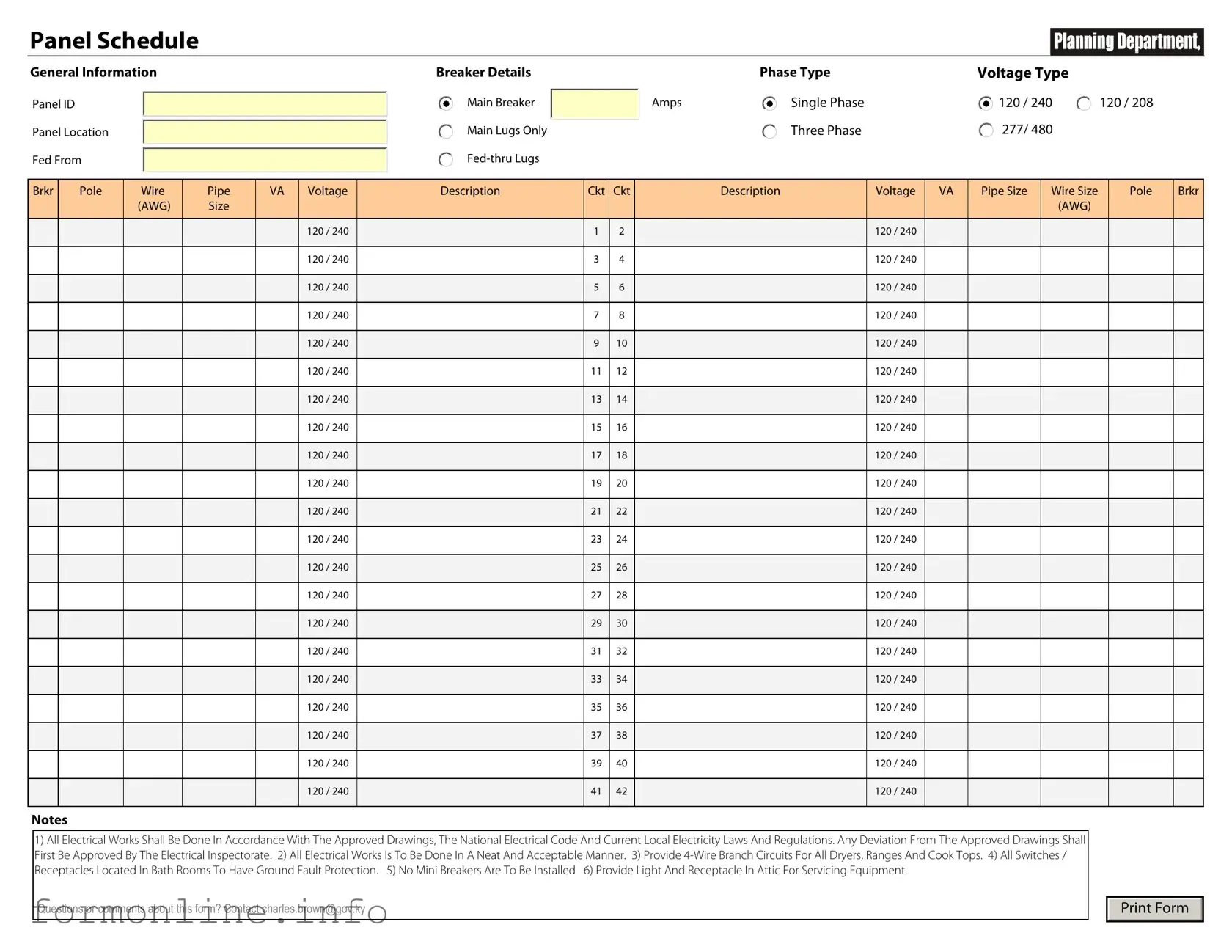
Preview - Electrical Panel Schedule Form
Panel Schedule
General Information
Panel ID
Panel Location
Fed From
Breaker Details
Main Breaker
Main Lugs Only
|
Phase Type |
Voltage Type |
|
Amps |
Single Phase |
120 / 240 |
120 / 208 |
|
Three Phase |
277/ 480 |
120 / 240 |
|
|
|
Brkr |
Pole |
Wire |
Pipe |
VA |
Voltage |
Description |
Ckt |
Ckt |
Description |
Voltage |
VA |
Pipe Size |
Wire Size |
Pole |
Brkr |
|
|
(AWG) |
Size |
|
|
|
|
|
|
|
|
|
(AWG) |
|
|
|
|
|
|
|
|
|
|
|
|
|
|
|
|
|
|
|
|
|
|
|
120 / 240 |
|
1 |
2 |
|
120 / 240 |
|
|
|
|
|
|
|
|
|
|
|
|
|
|
|
|
|
|
|
|
|
|
|
|
|
|
120 / 240 |
|
3 |
4 |
|
120 / 240 |
|
|
|
|
|
|
|
|
|
|
|
|
|
|
|
|
|
|
|
|
|
|
|
|
|
|
120 / 240 |
|
5 |
6 |
|
120 / 240 |
|
|
|
|
|
|
|
|
|
|
|
|
|
|
|
|
|
|
|
|
|
|
|
|
|
|
120 / 240 |
|
7 |
8 |
|
120 / 240 |
|
|
|
|
|
|
|
|
|
|
|
|
|
|
|
|
|
|
|
|
|
|
|
|
|
|
120 / 240 |
|
9 |
10 |
|
120 / 240 |
|
|
|
|
|
|
|
|
|
|
|
|
|
|
|
|
|
|
|
|
|
|
|
|
|
|
120 / 240 |
|
11 |
12 |
|
120 / 240 |
|
|
|
|
|
|
|
|
|
|
|
|
|
|
|
|
|
|
|
|
|
|
|
|
|
|
120 / 240 |
|
13 |
14 |
|
120 / 240 |
|
|
|
|
|
|
|
|
|
|
|
|
|
|
|
|
|
|
|
|
|
|
|
|
|
|
120 / 240 |
|
15 |
16 |
|
120 / 240 |
|
|
|
|
|
|
|
|
|
|
|
|
|
|
|
|
|
|
|
|
|
|
|
|
|
|
120 / 240 |
|
17 |
18 |
|
120 / 240 |
|
|
|
|
|
|
|
|
|
|
|
|
|
|
|
|
|
|
|
|
|
|
|
|
|
|
120 / 240 |
|
19 |
20 |
|
120 / 240 |
|
|
|
|
|
|
|
|
|
|
|
|
|
|
|
|
|
|
|
|
|
|
|
|
|
|
120 / 240 |
|
21 |
22 |
|
120 / 240 |
|
|
|
|
|
|
|
|
|
|
|
|
|
|
|
|
|
|
|
|
|
|
|
|
|
|
120 / 240 |
|
23 |
24 |
|
120 / 240 |
|
|
|
|
|
|
|
|
|
|
|
|
|
|
|
|
|
|
|
|
|
|
|
|
|
|
120 / 240 |
|
25 |
26 |
|
120 / 240 |
|
|
|
|
|
|
|
|
|
|
|
|
|
|
|
|
|
|
|
|
|
|
|
|
|
|
120 / 240 |
|
27 |
28 |
|
120 / 240 |
|
|
|
|
|
|
|
|
|
|
|
|
|
|
|
|
|
|
|
|
|
|
|
|
|
|
120 / 240 |
|
29 |
30 |
|
120 / 240 |
|
|
|
|
|
|
|
|
|
|
|
|
|
|
|
|
|
|
|
|
|
|
|
|
|
|
120 / 240 |
|
31 |
32 |
|
120 / 240 |
|
|
|
|
|
|
|
|
|
|
|
|
|
|
|
|
|
|
|
|
|
|
|
|
|
|
120 / 240 |
|
33 |
34 |
|
120 / 240 |
|
|
|
|
|
|
|
|
|
|
|
|
|
|
|
|
|
|
|
|
|
|
|
|
|
|
120 / 240 |
|
35 |
36 |
|
120 / 240 |
|
|
|
|
|
|
|
|
|
|
|
|
|
|
|
|
|
|
|
|
|
|
|
|
|
|
120 / 240 |
|
37 |
38 |
|
120 / 240 |
|
|
|
|
|
|
|
|
|
|
|
|
|
|
|
|
|
|
|
|
|
|
|
|
|
|
120 / 240 |
|
39 |
40 |
|
120 / 240 |
|
|
|
|
|
|
|
|
|
|
|
|
|
|
|
|
|
|
|
|
|
|
|
|
|
|
120 / 240 |
|
41 |
42 |
|
120 / 240 |
|
|
|
|
|
|
|
|
|
|
|
|
|
|
|
|
|
|
|
|
|
Notes
1)All Electrical Works Shall Be Done In Accordance With The Approved Drawings, The National Electrical Code And Current Local Electricity Laws And Regulations. Any Deviation From The Approved Drawings Shall First Be Approved By The Electrical Inspectorate. 2) All Electrical Works Is To Be Done In A Neat And Acceptable Manner. 3) Provide
Receptacles Located In Bath Rooms To Have Ground Fault Protection. 5) No Mini Breakers Are To Be Installed 6) Provide Light And Receptacle In Attic For Servicing Equipment.
Questions or comments about this form? Contact charles.brown@gov.ky
Print Form
Other PDF Templates
Acord 130 - Seasonal employment details ensure clarity regarding fluctuating workforce levels throughout the year.
Texas Real Estate Contract - The contract allows for negotiation of the timeframes for financing and inspections.
When engaging in the sale of a motorcycle in New York, it is crucial to have a properly completed Motorcycle Bill of Sale form, which acts as a legal record of the transaction. This document not only captures vital details about the buyer, seller, and motorcycle but also reinforces the legality of the sale. For those looking to obtain a comprehensive form, you can access it through autobillofsaleform.com/motorcycle-bill-of-sale-form/new-york-motorcycle-bill-of-sale-form/.
What Is a Lien Waiver for Construction - The document signifies the contractor's commitment to deliver quality work without pending claims.
Documents used along the form
The Electrical Panel Schedule form is an essential document used in electrical installations and maintenance. It outlines the distribution of electrical circuits and their respective loads within a panel. Several other forms and documents complement this schedule, ensuring comprehensive documentation and safety compliance in electrical work.
- Load Calculation Worksheet: This document details the calculations used to determine the total electrical load for a building or specific area. It helps ensure that the electrical system can handle the demand without overloading.
- Circuit Directory: A circuit directory provides a list of all circuits within an electrical panel, indicating their respective locations and the devices they power. This aids in quick identification and troubleshooting.
- Service Entrance Schedule: This form outlines the main service entrance for the electrical supply to a building. It includes information about the service size, voltage, and type of service being provided.
- Homeschool Letter of Intent: This essential form notifies the state of a family's decision to homeschool and outlines the basic information required by law. For more details, visit the Homeschool Letter of Intent.
- Panelboard Installation Instructions: These instructions guide the proper installation and configuration of the panelboard. They include safety warnings, wiring diagrams, and operational guidelines.
- Inspection Report: An inspection report documents the findings of an electrical inspection. It highlights any issues found during the inspection and may recommend corrective actions to ensure compliance with safety standards.
These documents work together to ensure that electrical systems are safe, efficient, and compliant with regulations. Properly maintaining and utilizing these forms can significantly enhance the reliability of electrical installations.
Similar forms
The Electrical Load Calculation form is similar to the Electrical Panel Schedule in that both documents are essential for understanding the electrical demands of a building. The Load Calculation form outlines the anticipated electrical load based on various factors such as the size of the building, the number of electrical appliances, and the type of occupancy. This information helps ensure that the electrical system is designed to handle the expected load, just as the Panel Schedule details the specific circuits and their respective loads, providing a comprehensive overview of the electrical distribution system.
The Circuit Directory serves a function akin to the Electrical Panel Schedule by detailing the specific circuits connected to the electrical panel. It lists each circuit along with its corresponding breaker size and the areas or appliances it serves. This document is crucial for maintenance and troubleshooting, as it allows electricians and homeowners to quickly identify which circuit controls what part of the electrical system, similar to how the Panel Schedule organizes this information for easy reference.
The One-Line Diagram is another document that shares similarities with the Electrical Panel Schedule. This diagram visually represents the electrical system's layout, including the electrical panel, circuits, and major components. While the Panel Schedule provides a written format of circuit loads and breaker sizes, the One-Line Diagram offers a graphical representation, making it easier to understand the overall system at a glance. Both documents work together to provide a complete picture of the electrical setup.
The Service Entrance Diagram outlines how electricity enters a building and is comparable to the Electrical Panel Schedule in that it details critical components of the electrical system. This document shows the main service disconnect, meter location, and the main panel, much like the Panel Schedule describes how power is distributed throughout the circuits. Understanding both documents is essential for ensuring that the electrical service is safe and reliable.
The Load Balancing Report is similar to the Electrical Panel Schedule in its focus on ensuring that electrical loads are evenly distributed across circuits. This report analyzes the load on each circuit and identifies any imbalances that could lead to overheating or circuit failure. The Panel Schedule assists in this process by providing the necessary data on each circuit's load, allowing for informed adjustments to be made to maintain balance and safety.
Understanding the importance of verifying employment details can be crucial; for that reason, many individuals seek access to a form that assists in such confirmations. For clear guidance on completing this process, one may refer to the comprehensive Employment Verification document available at the Florida Employment Verification form. This resource is vital for securing necessary endorsements during various evaluations, such as financial applications or assessments of job history.
The Maintenance Log for electrical systems parallels the Electrical Panel Schedule by tracking the performance and service history of the electrical panel and its circuits. This log includes records of inspections, repairs, and any modifications made to the system. Both documents are vital for ensuring that the electrical system operates efficiently and safely, as they provide a historical context for ongoing maintenance needs.
The Wiring Diagram is another document that complements the Electrical Panel Schedule. It illustrates the actual wiring connections and configurations within the electrical system. While the Panel Schedule focuses on load management and circuit details, the Wiring Diagram provides a technical view of how those circuits are physically arranged. Together, they ensure that electricians have both the functional and physical aspects of the system at their disposal.
The Electrical Inspection Report is similar to the Electrical Panel Schedule in that it provides a comprehensive assessment of the electrical system's compliance with safety standards. This report is typically generated after an inspection and includes findings related to the panel, circuits, and overall system integrity. The Panel Schedule supports this report by offering detailed information about circuit loads and configurations, which inspectors use to evaluate safety and compliance.
Finally, the Energy Usage Report is comparable to the Electrical Panel Schedule in that it analyzes how energy is consumed throughout a building. This report breaks down energy usage by circuit or appliance, allowing homeowners and facility managers to identify areas where energy efficiency can be improved. The Panel Schedule aids in this analysis by providing the necessary circuit information, helping to pinpoint where adjustments can be made for better energy management.
Dos and Don'ts
When filling out the Electrical Panel Schedule form, it's important to follow specific guidelines to ensure accuracy and compliance. Here are seven things you should and shouldn't do:
- Do double-check all information for accuracy before submission.
- Do use clear and legible handwriting or type the information.
- Do include all required fields as specified in the form.
- Do ensure that the electrical load calculations are correct.
- Don't leave any fields blank unless they are marked as optional.
- Don't use abbreviations that may cause confusion.
- Don't forget to sign and date the form before submitting it.
Key takeaways
When filling out and using the Electrical Panel Schedule form, keep these key takeaways in mind:
- Accuracy is Crucial: Ensure that all information is entered correctly. Mistakes can lead to safety hazards or operational issues.
- Label Each Circuit Clearly: Each circuit should have a clear and descriptive label. This helps in identifying circuits quickly during maintenance or troubleshooting.
- Include Load Calculations: Document the load calculations for each circuit. This information is essential for understanding the capacity and ensuring the panel is not overloaded.
- Regular Updates are Necessary: Keep the schedule updated whenever changes are made. This includes adding new circuits or modifying existing ones.
- Consult with Professionals: If unsure about any aspect of the form, seek advice from a qualified electrician. Their expertise can prevent costly mistakes.
How to Use Electrical Panel Schedule
After obtaining the Electrical Panel Schedule form, you will need to complete it accurately to ensure proper documentation of the electrical system. Follow the steps below to fill out the form correctly.
- Start by entering the Project Name at the top of the form. This identifies the specific project associated with the electrical panel.
- Next, fill in the Panel Name or Number. This helps to distinguish between multiple panels in the project.
- Indicate the Location of the panel within the building. This provides clarity on where the panel is situated.
- Enter the Voltage Rating of the panel. This is typically specified in volts (e.g., 120V, 240V).
- Document the Phase type, which can be single-phase or three-phase, depending on the system used.
- Specify the Amperage Rating of the panel. This indicates the maximum current the panel can handle.
- List the Breaker Sizes for each circuit. Include the amperage rating for each breaker.
- Provide a description for each circuit. This should detail the purpose or load served by the circuit.
- Include the Load Calculation for each circuit, which helps in assessing the overall load on the panel.
- Finally, review the completed form for accuracy and sign it if required. This ensures that all information is correct and verified.