Fill Out a Valid Megger Test Form
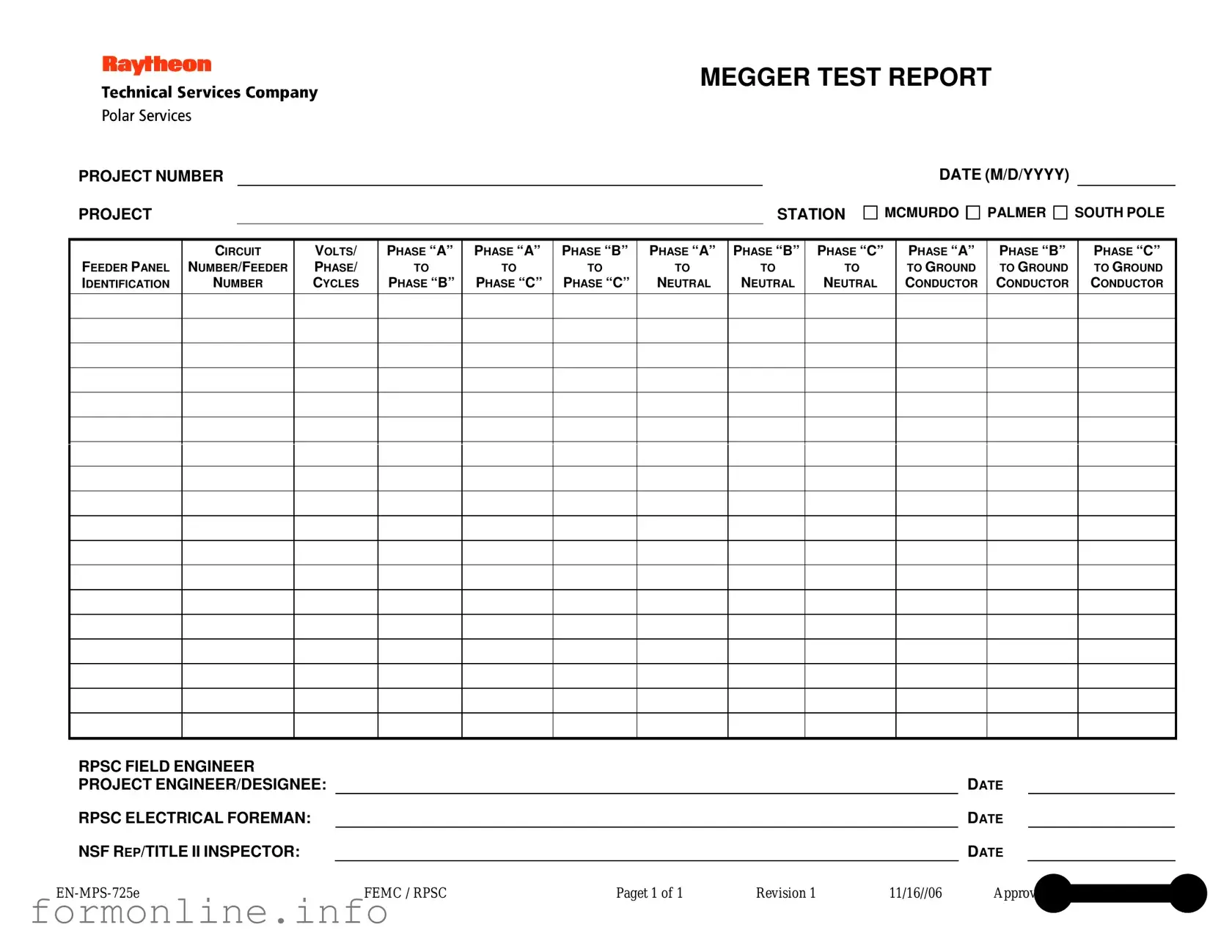
The Megger Test form serves as an essential document in assessing the electrical integrity of various systems within a project. This report includes critical details such as the project number, station, and date, ensuring that all information is accurately recorded for future reference. It identifies specific feeder panels and circuit numbers, allowing for precise testing of electrical phases. The form captures voltage readings across different phases, including Phase “A” to Phase “B,” Phase “A” to Phase “C,” and Phase “B” to Phase “C.” Additionally, it provides measurements from each phase to neutral and ground, which are vital for determining the safety and functionality of the electrical system. The roles of key personnel, such as the RPSC field engineer and project engineer, are clearly defined, with spaces allocated for their signatures and dates. This structured approach not only promotes accountability but also ensures that all necessary inspections are documented. The form is a crucial tool for maintaining compliance and safety standards in electrical installations, reflecting the commitment to quality and thoroughness in every project.
Common mistakes
-
Inaccurate Project Number: Ensure that the project number matches the one assigned to the specific test. Using an incorrect number can lead to confusion and misfiled reports.
-
Missing Dates: Always fill in the date in the correct format (M/D/YYYY). Omitting this information can delay processing and verification of the test results.
-
Incorrect Voltage/Phase/Cycles: Double-check the voltage, phase, and cycles entered. Errors in these values can result in misleading test outcomes and affect safety measures.
-
Omitting Signatures: Ensure all required signatures are present. Missing signatures from the RPSC field engineer, project engineer, or inspector may invalidate the report.
Preview - Megger Test Form
MEGGER TEST REPORT
PROJECT NUMBER
PROJECT |
|
STATION |
DATE (M/D/YYYY)
MCMURDO 
 PALMER
 SOUTH POLE
FEEDER PANEL IDENTIFICATION
CIRCUIT
NUMBER/FEEDER
NUMBER
VOLTS/
PHASE/
CYCLES
PHASE “A”
TO
PHASE “B”
PHASE “A”
TO
PHASE “C”
PHASE “B”
TO
PHASE “C”
PHASE “A”
TO
NEUTRAL
PHASE “B”
TO
NEUTRAL
PHASE “C”
TO
NEUTRAL
PHASE “A”
TO GROUND CONDUCTOR
PHASE “B”
TO GROUND CONDUCTOR
PHASE “C”
TO GROUND CONDUCTOR
RPSC FIELD ENGINEER |
|
|
|
|
|
|
PROJECT ENGINEER/DESIGNEE: |
|
|
|
|
DATE |
|
RPSC ELECTRICAL FOREMAN: |
|
|
|
|
DATE |
|
NSF REP/TITLE II INSPECTOR: |
|
|
|
|
DATE |
|
FEMC / RPSC |
Paget 1 of 1 |
Revision 1 |
11/16//06 |
Approved by Wayne L. Cornell |
||
Other PDF Templates
T47 Paralympics - The T-47 enhances transparency in real estate dealings.
In understanding the importance of a Release of Liability form, it's essential to recognize that it serves as a crucial tool for both organizers and participants to acknowledge the inherent risks associated with various activities. These documents not only help mitigate potential disputes but also ensure that all parties are informed and agree to the terms before engaging in potentially hazardous events. To delve deeper into the specifics of this legal agreement, you can learn more about its usage and significance.
Basketball Player Evaluation - Review 3-point shooting capability for range and accuracy.
Documents used along the form
The Megger Test form is a critical document used to assess the insulation resistance of electrical systems. It is often accompanied by several other forms and documents that provide essential information and context for the testing process. Below is a list of related documents commonly used alongside the Megger Test form.
- Inspection Checklist: This document outlines the specific items to be inspected prior to conducting the Megger Test. It ensures that all necessary precautions and preparations are made to guarantee safety and accuracy during testing.
- Test Plan: A detailed description of the testing procedures, including the objectives, methodologies, and equipment to be used. This plan serves as a roadmap for the testing process and helps in maintaining consistency across tests.
- Calibration Certificate: This document verifies that the Megger testing equipment has been calibrated according to industry standards. It provides assurance that the measurements taken during the test are reliable and accurate.
- Safety Data Sheet (SDS): This document contains information about the hazards associated with materials used in the testing process. It outlines safety precautions and emergency procedures to protect personnel during the test.
- Field Notes: A record of observations and any anomalies noted during the testing process. Field notes can provide valuable context for interpreting test results and may highlight areas needing further investigation.
- Test Results Summary: A concise report that summarizes the findings of the Megger Test. This document presents the key data in an accessible format for stakeholders to review and understand the test outcomes.
- Maintenance Log: A record of any maintenance performed on the electrical systems being tested. This log can help identify patterns or issues that may affect insulation resistance and overall system performance.
- General Power of Attorney Form: This form in Georgia grants authority to an individual to make decisions on your behalf, particularly in financial matters. For more information, visit georgiapdf.com/.
- Final Report: A comprehensive document that includes all relevant test data, analysis, and recommendations based on the Megger Test and associated findings. This report serves as a formal conclusion to the testing process and aids in decision-making for future actions.
Each of these documents plays a vital role in ensuring that the Megger Test is conducted effectively and that the results are reliable. Together, they contribute to a thorough understanding of the electrical system's condition and help maintain safety and compliance in electrical work.
Similar forms
The Megger Test form shares similarities with a Standard Electrical Inspection Report. Both documents serve to record and communicate the results of electrical testing. The Standard Electrical Inspection Report typically includes details about the circuits tested, voltage levels, and any findings related to safety and compliance. Like the Megger Test form, it emphasizes clarity and accuracy to ensure that all stakeholders understand the condition of the electrical systems being evaluated.
Just as the various electrical test reports play a critical role in ensuring the safety and efficiency of electrical systems, the Homeschool Letter of Intent serves an essential function for families considering homeschooling in Virginia. This formal document is not only a notification to the local school division but also represents a commitment to providing a well-rounded educational experience outside the conventional school environment. Understanding its components can enable families to navigate their homeschooling journey confidently.
An Equipment Testing Report is another document akin to the Megger Test form. This report focuses on the performance and safety of specific electrical equipment. It includes measurements and observations similar to those found in the Megger Test, such as insulation resistance and voltage levels. Both documents aim to provide a clear assessment of electrical safety and functionality, ensuring that the equipment meets necessary standards.
The Circuit Analysis Report is also comparable to the Megger Test form. This report delves into the behavior of electrical circuits under various conditions. Like the Megger Test, it provides detailed measurements and analysis of circuit performance, helping engineers identify potential issues. Both reports play a critical role in maintaining electrical system integrity and reliability.
Dos and Don'ts
When filling out the Megger Test form, it's essential to approach the task with care. Here’s a list of things you should and shouldn’t do:
- Do ensure all fields are completed accurately. Missing information can lead to confusion later.
- Do double-check the project number and station name. Accuracy is key for record-keeping.
- Do use clear and legible handwriting or type the information if possible. This helps avoid misinterpretation.
- Do verify the voltage and phase details before submission. Incorrect values can result in significant issues.
- Don’t leave any sections blank. If a section is not applicable, mark it clearly instead of skipping it.
- Don’t rush through the form. Taking your time can prevent mistakes that might require corrections later.
Following these guidelines will help ensure that your Megger Test form is filled out correctly and efficiently.
Key takeaways
Filling out and utilizing the Megger Test form is crucial for ensuring the safety and reliability of electrical systems. Here are some key takeaways to keep in mind:
- Project Identification: Always start by clearly entering the project number and station name. This information helps in tracking and referencing the test results later.
- Date Entry: The date should be filled out in the format M/D/YYYY. Accurate dating is essential for maintaining an organized record.
- Panel Identification: Specify the feeder panel identification. This detail is vital for identifying which panel the test results pertain to.
- Circuit Number: Record the circuit number or feeder number. This helps in pinpointing the exact circuit that has been tested.
- Voltage and Phase Information: Clearly indicate the voltage, phase, and cycles. This data is necessary for understanding the operational conditions during the test.
- Grounding Measurements: Make sure to measure and record the values for phase-to-ground conductors. These readings are crucial for assessing electrical safety.
- Signatures: Don’t forget to have the project engineer, electrical foreman, and any inspectors sign the form. Their approval signifies that the test has been conducted properly and the results are valid.
By keeping these points in mind, you can ensure that the Megger Test form is filled out accurately and effectively. Proper documentation is key to maintaining electrical safety standards.
How to Use Megger Test
Filling out the Megger Test form is a straightforward process that requires attention to detail. This form collects essential data related to electrical testing, and accurate information is crucial for maintaining safety and compliance standards. Follow these steps to ensure that you complete the form correctly.
- Start by entering the Project Number at the top of the form.
- Next, fill in the Project Station name, choosing from McMurdo, Palmer, or South Pole.
- Enter the Date in the format M/D/YYYY.
- Identify the Feeder Panel by providing its identification.
- Write the Circuit Number/Feeder Number as applicable.
- Fill in the Volts/Phase/Cycles information.
- Complete the measurements for the following phases:
- Phase “A” to Phase “B”
- Phase “A” to Phase “C”
- Phase “B” to Phase “C”
- Phase “A” to Neutral
- Phase “B” to Neutral
- Phase “C” to Neutral
- Phase “A” to Ground
- Phase “B” to Ground
- Phase “C” to Ground
- Designate the RPSC Field Engineer responsible for this test.
- Have the Project Engineer/Designee sign and date the form.
- Next, the RPSC Electrical Foreman should sign and date the form as well.
- Finally, ensure the NSF Rep/Title II Inspector signs and dates the form.
Once you have filled out the form completely, it will be ready for submission. Make sure to double-check all entries for accuracy before finalizing the document. This will help prevent any issues down the line.